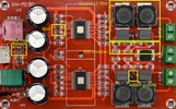
I’ve been using a TPA3116D2 amplifier board from aliexpress for months, until it failed - left channel started popping every second or so. I fixed the board and did some sanity checking/fixing.
The fault
The left channel is working for a second, then the speaker pops loudly, amp is silent for a second, pops back to working and this repeats.
At first, I didn’t realize there is actually a sound inbetween, so I discounted it as the IC being dead. Unfortunately, the ICs are not really available these days from any reputable distributor, so I ordered a replacement from Aliexpress. After swapping it over, the pops were less frequenty, but still present nonetheless. The fault is not with the IC, more debugging is needed.
Circuit
To analyze the circuit, a schematic is nice to have. Lucky for me, the TPA3116D2 datasheet from TI has typical application that is practically identical to the board in question - I’m actually surprised they didn’t copy it completely with all the values and reference designators (that would’ve made my time even easier).
Some of these boards are known to have wrong IC setup. One amp board I had set up both ICs into master mode, fighting over clock on the SYNC pin. However, these boards are both set up for 26dB Master/Slave configuratio.
There’s a FAULTZ output on pin 3 of the IC. Same as the TI reference
application, it is connected to pin 2 (SDZ) and pulled up by a 100k
resistor. Scoping this pin, it indeed pulls low with the pop event and
releases a while after that, trying to recover.
Fault reasons and the fix
The FAULTZ condition is asserted on multiple conditions:
- Overcurrent (shorted output)
- Overtemperature
- DC output voltage
In my case, the output measures good, including all passive components (can be roughly measured in circuit, though I did desolder the filter caps to check), and temperature is low (only drawing 0.1A during testing, case not hot to the touch). The DC output voltage could be the culprit.
Checking the “DC Detect Protection” paragraph in the datasheets states “Take care to match the impedance seen at the positive and negative inputs to avoid nuisance DC detect faults.” - this could be it. The input caps measure good - except for the input capacitors having different color on this channel.
Given the difference in color, I suspect they came off different, quite possibly from different manufacturers - and while working fine at first, as they age differently, the mismatch caused internal circuitry in the TPA3116 to believe there is a DC bias on the input and trigger the fault.
The capacitors used originally are 1.5µF, which I don’t have. At first, I actually mis-read the RLC meter and fitted 1nF capacitor as a replacement - resulting in a very quiet output, but the fault was fixed. Comparing that to the other channel, I realized the problem and fitted 1µF capacitors. Looking into datasheet for possible values, they form a high-pass filter with the input impedance and need to be selected based on the input impedance configured.
For 26dB amplification the input impedance is 30 kΩ, plugging that into the equation given in the datasheet:
$f = { 1 \over 2 \pi Z_i C_i } = {1 \over 2 \pi 30 \cdot 10^3 \cdot 1 \cdot 10^{-6}} = 5.32 Hz$
This is fine in my book, I’m not looking for super low frequencies today.
Other problems
There is quite a bit of noise on the output on higher amplifications. Some of it comes out of my PC I’m sure, but I decided to investigate how the board layout follows recommendations. The datasheet gives recommendations and a layout example, but this board does nothing listed there. All the caps are far away from the ICs (I presume to clear the heatsink), ground and power rails sneak all around the board and the output filter is not even grounded. I fixed the last thing and grounded the output filter at least, not that it made any difference - but I’m not going to invest more time to fix anything here. It would be better to make a custom board and move the ICs there.
