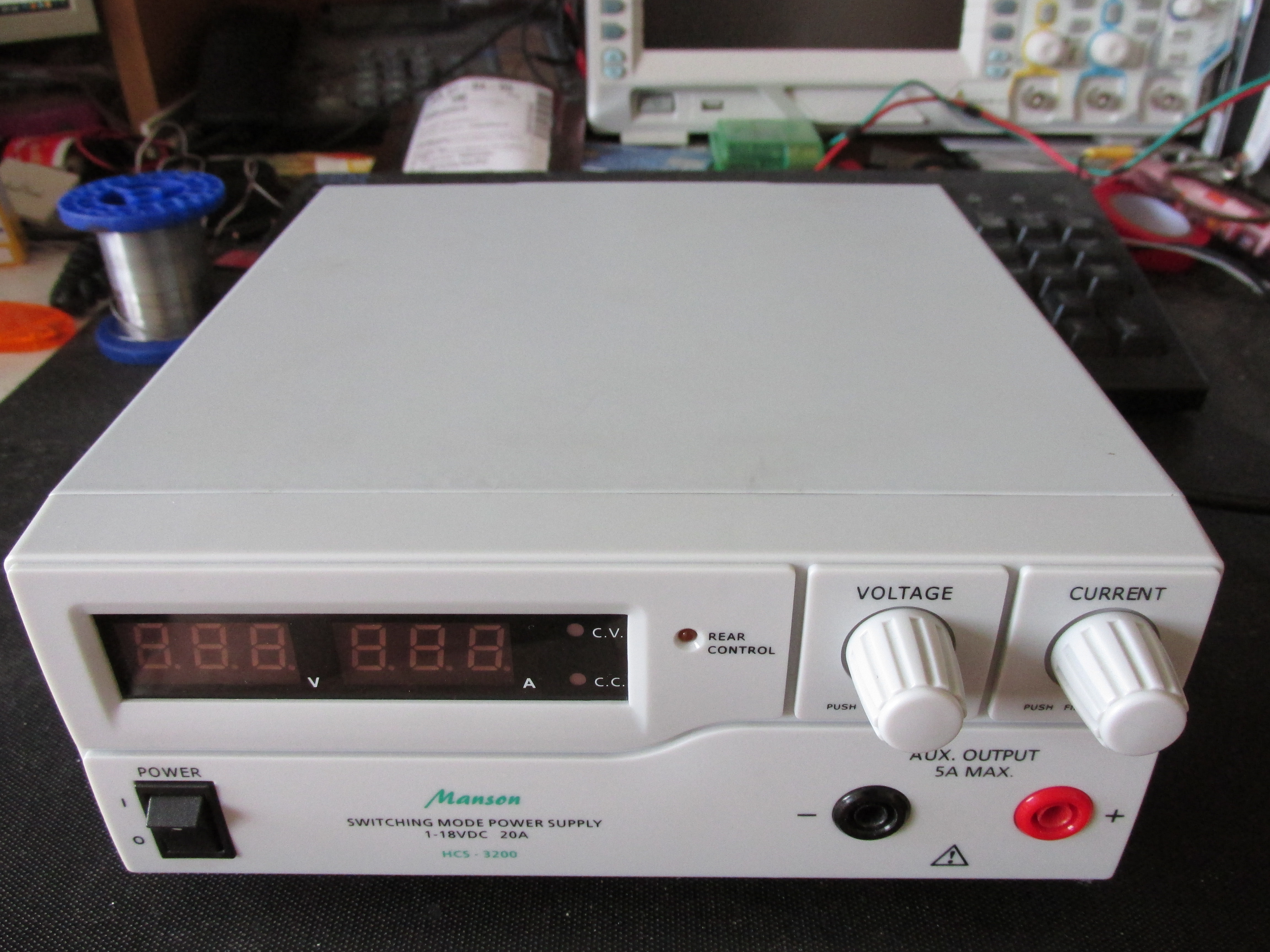
I’ve been using my Manson powersupply for some time and have been happy with it. It works like a charm, has a lot of power, and can be easily controlled via USB interface (serial emulation). The only downside is the fan, although thermally controlled, it’s real noisy when it’s running. As I replaced it with a new one, I took a few photos of the internals.
I have to mention the fan is replaceable without dismantling the whole power supply. You might want to do this in an attempt of not losing the warranty, unfortunately, the connector is not accessible this way, and you’d have to desolder the cables from the fan. I opened the whole thing though, since I wanted to take these photos, and there was no warranty sticker on mine.
To open the case, you need to unscrew the bottom and back screws, push back the two plastic thingies on the sides, holding the metal casing onto the plastic front panel. When it’s done, the metal case will slide to the back (plastic front stays in place). You can help yourself by bending the sides a bit, since the hooks are tight.
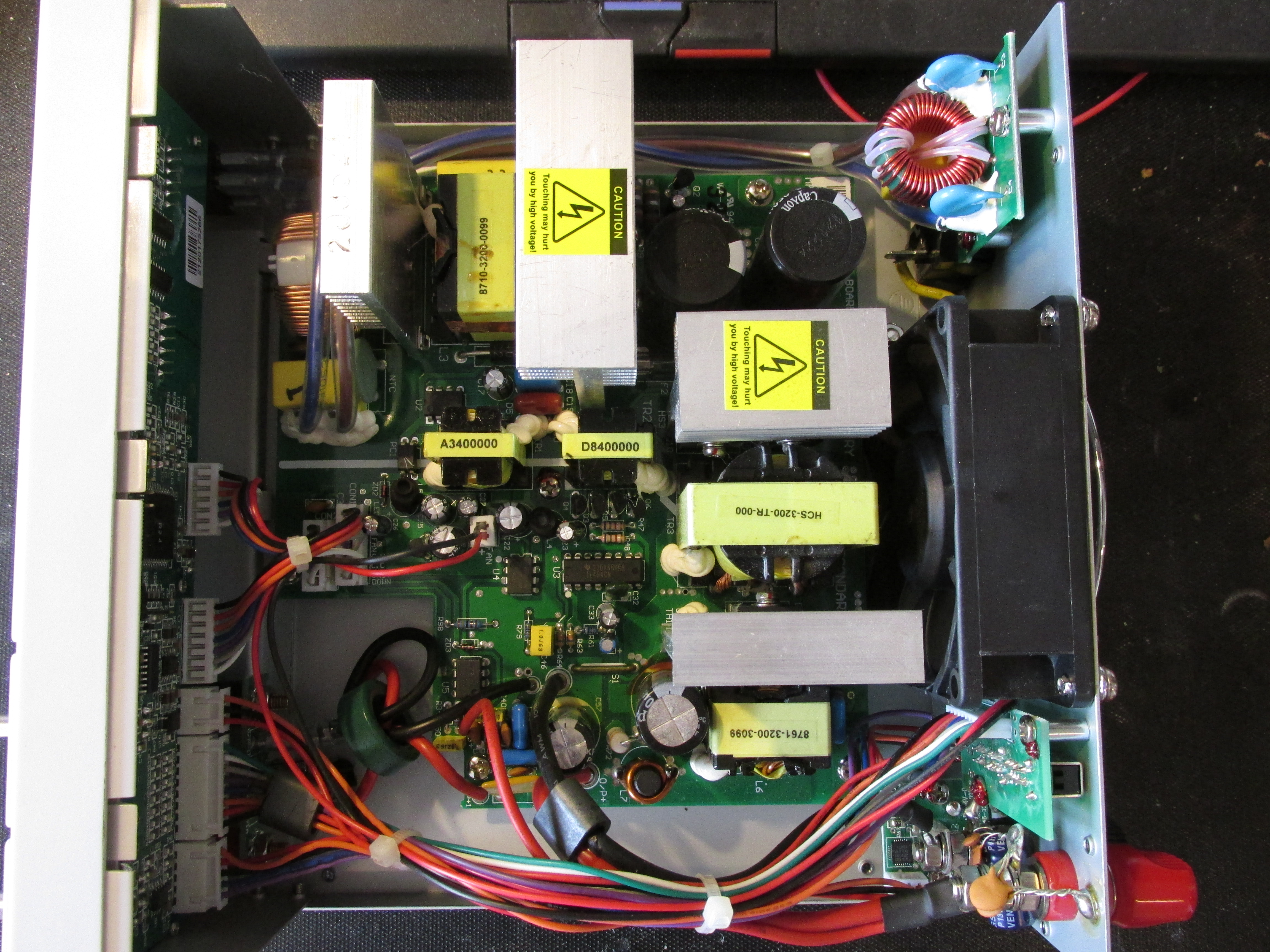
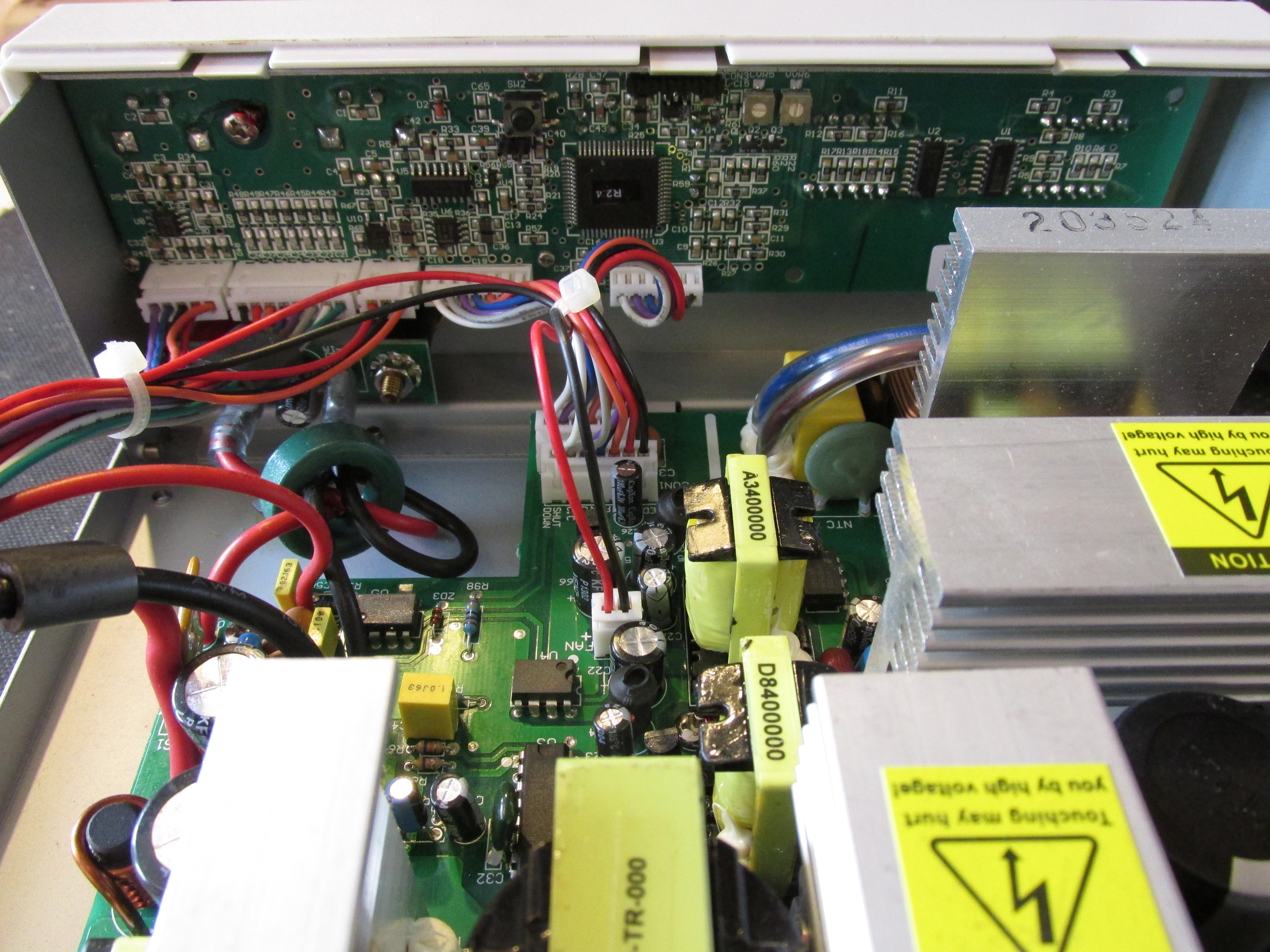
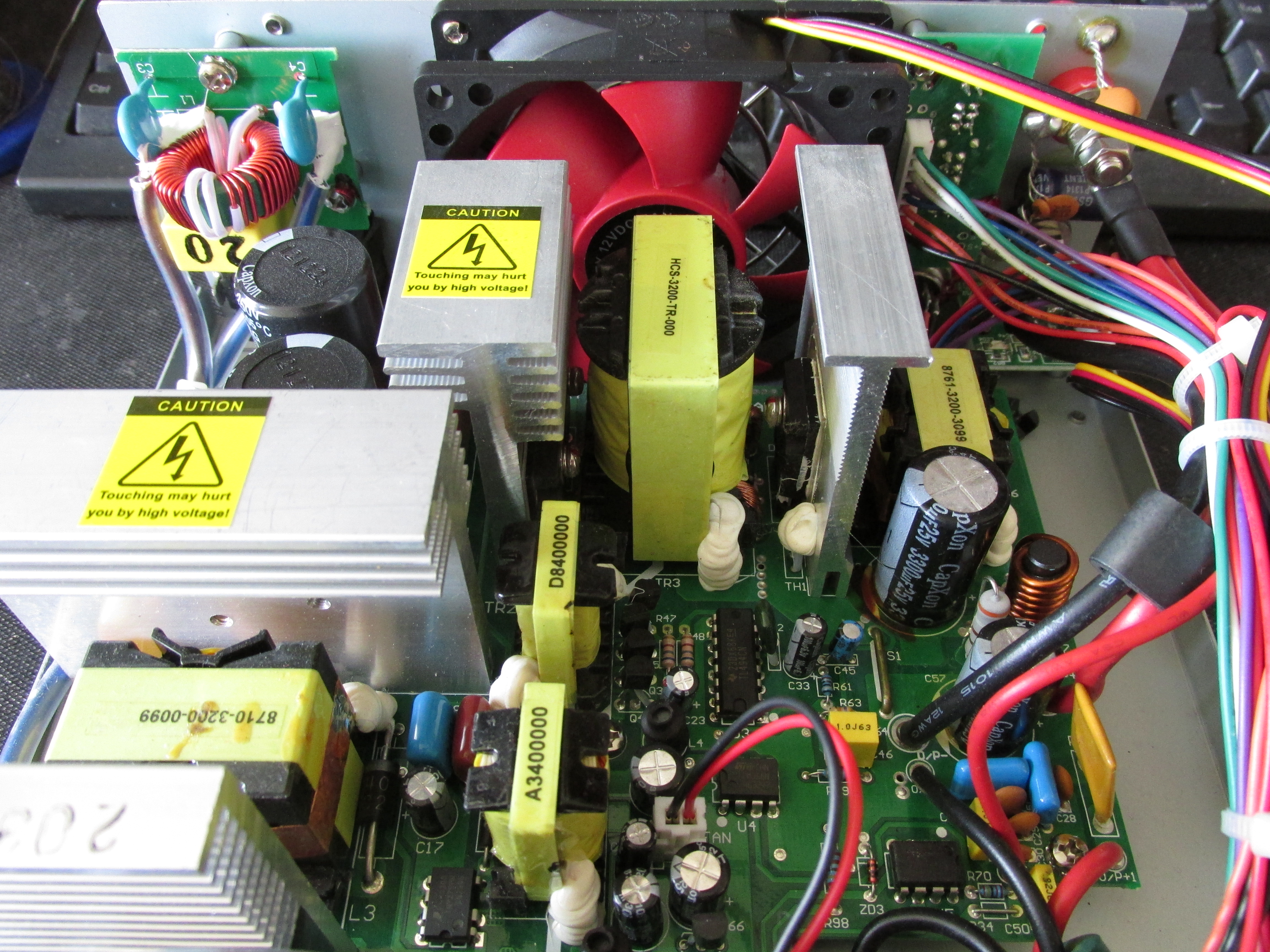
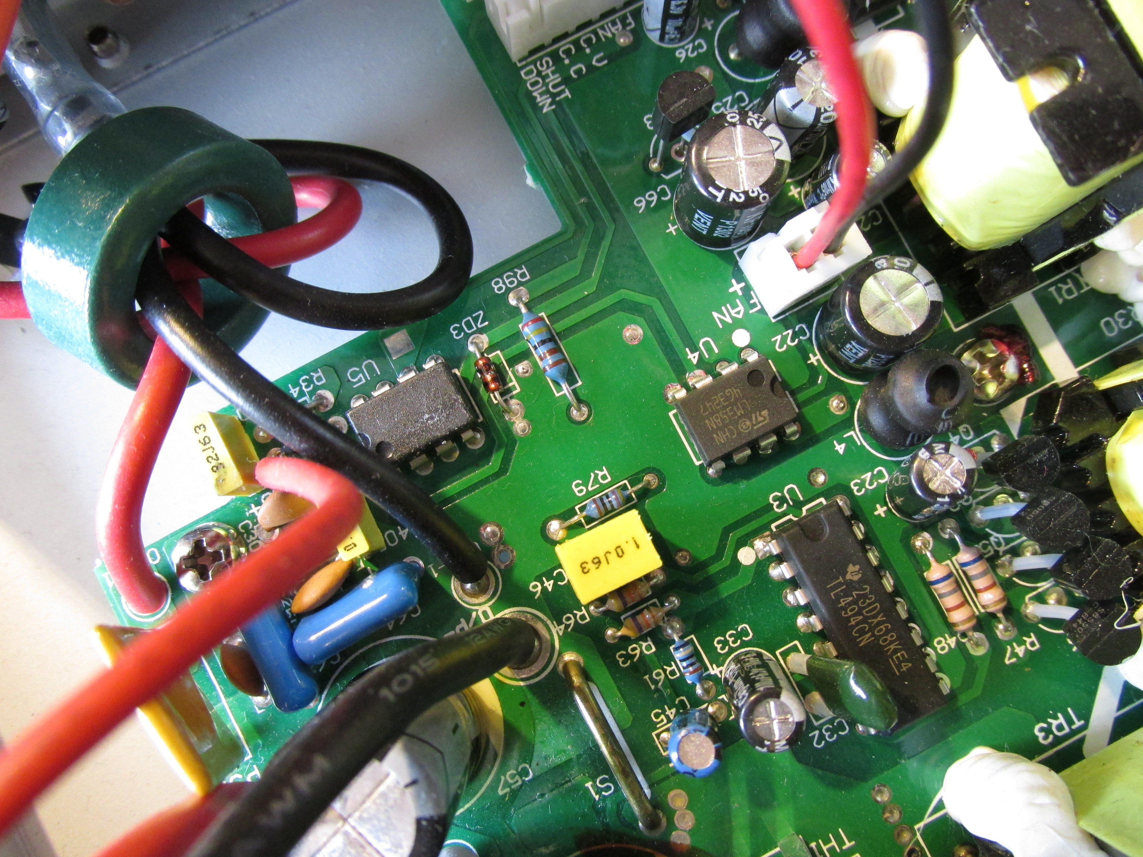
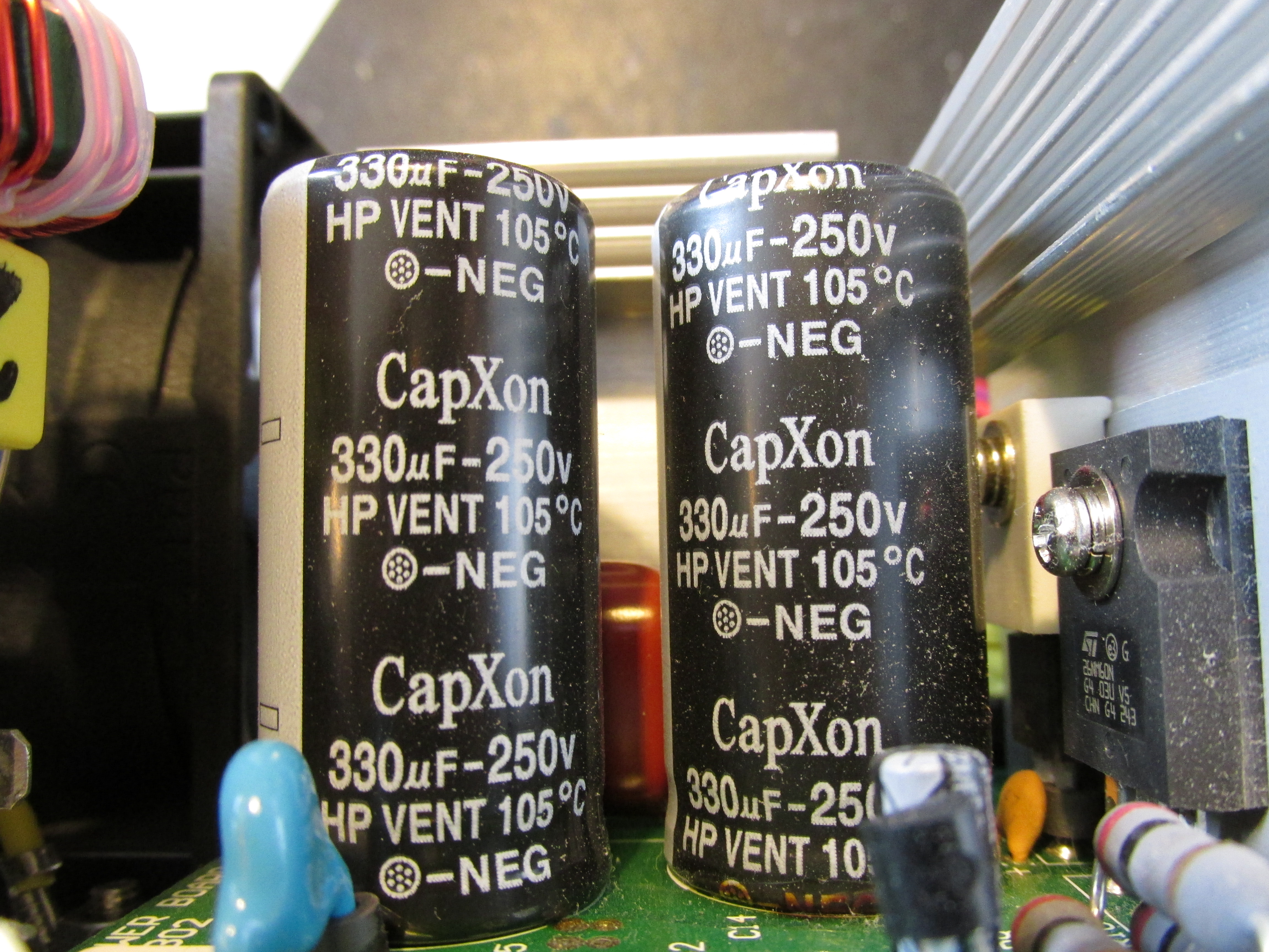
Inside, there are a few boards. The big board is the supply itself, with primary and secondary part nicely split, driven by a TL494, with some ordinary LM358s, pretty beafy transformers and a lot of CapXon caps. I haven’t found the reference, and it is probably generated on the MCU board.
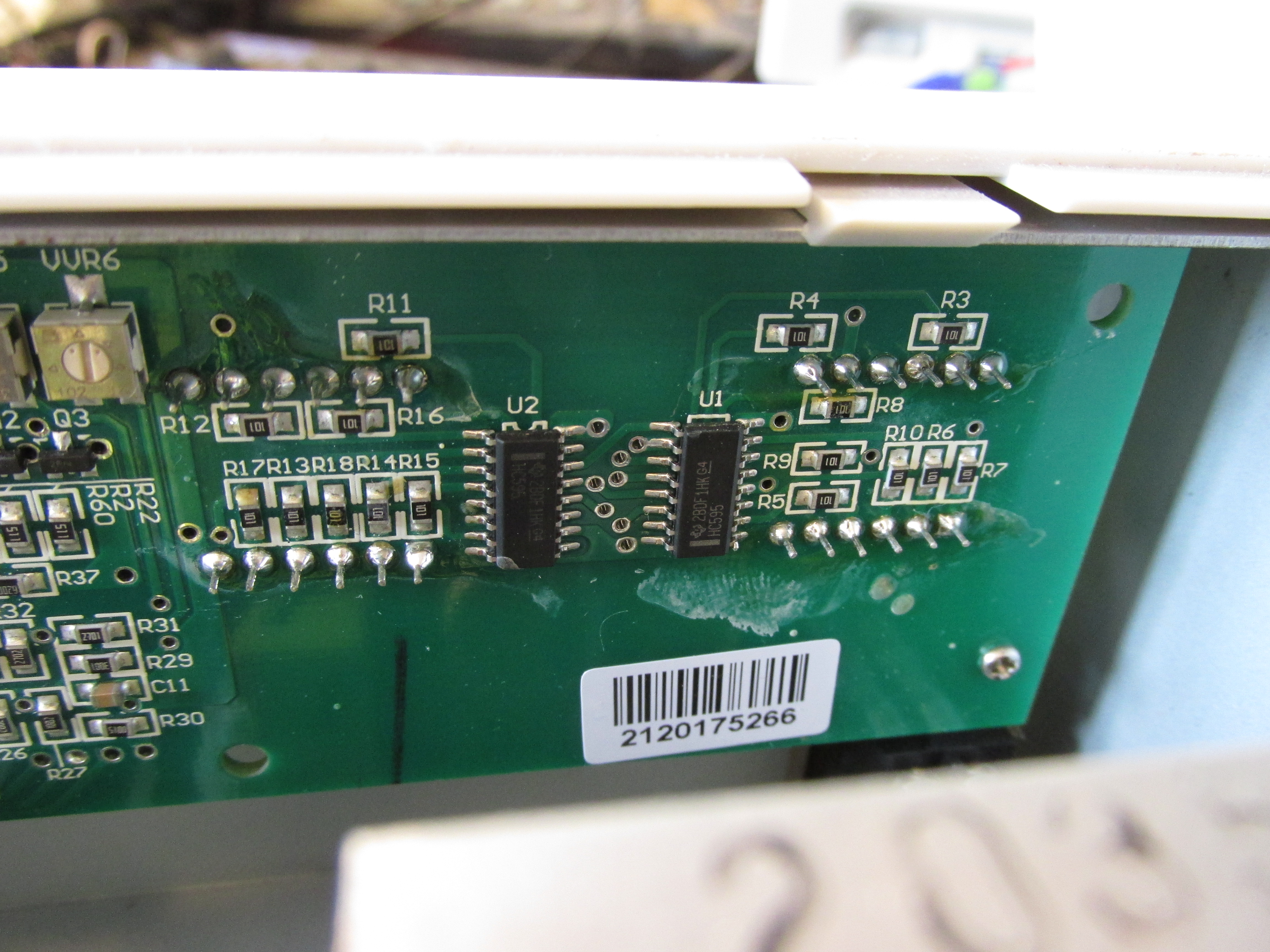
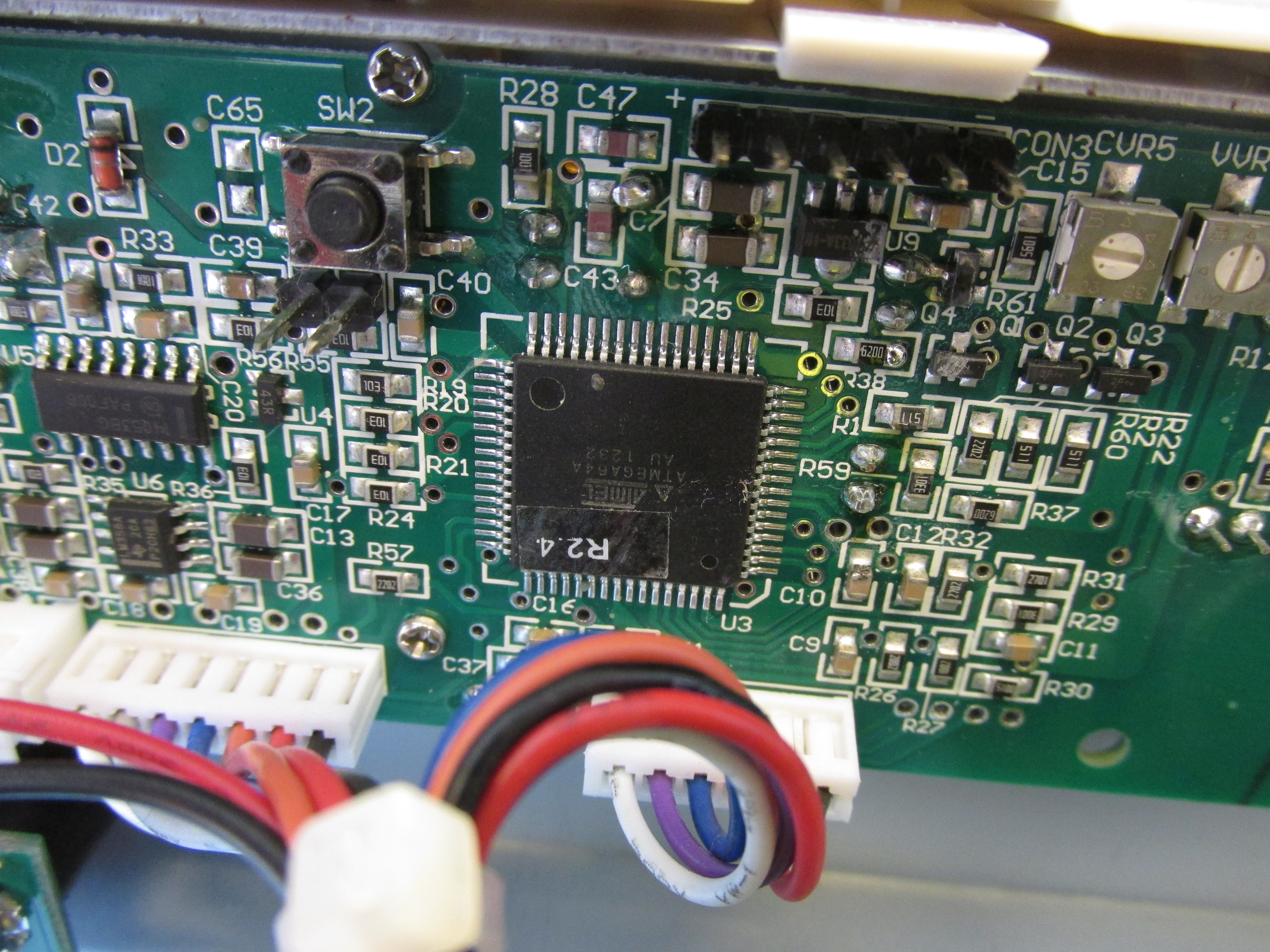
The MCU board, together with the front panel controls, contains an ATMega64A processor, some more LM358s, MC14053 analog multiplex, some trimmers (presumably for adjusting voltage/current readouts), and a lot of digital stuff.
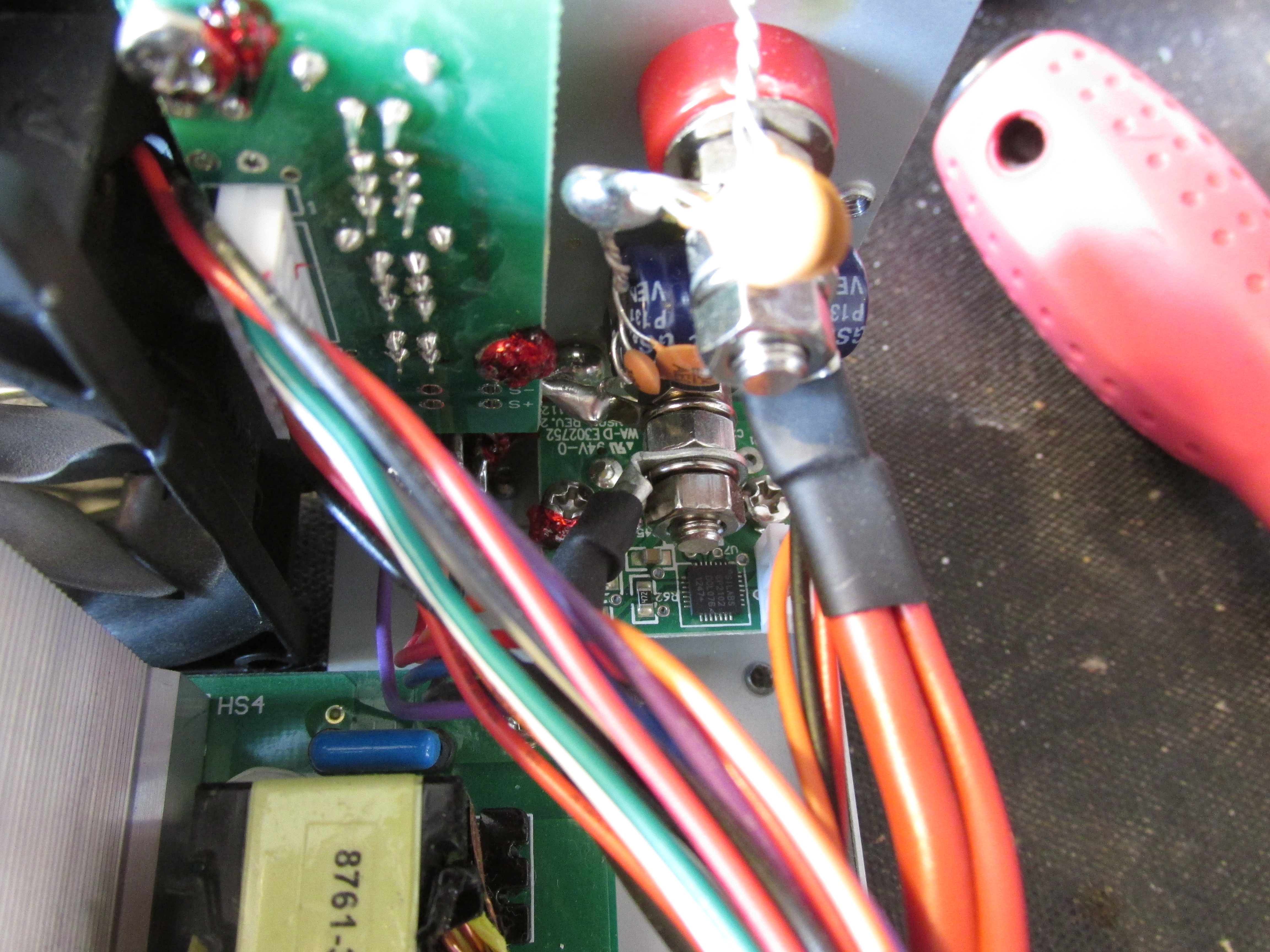
There are a few more boards, but nothing really interesting: a input power filter, rear switch board, and CP2102 USB-UART bridge.
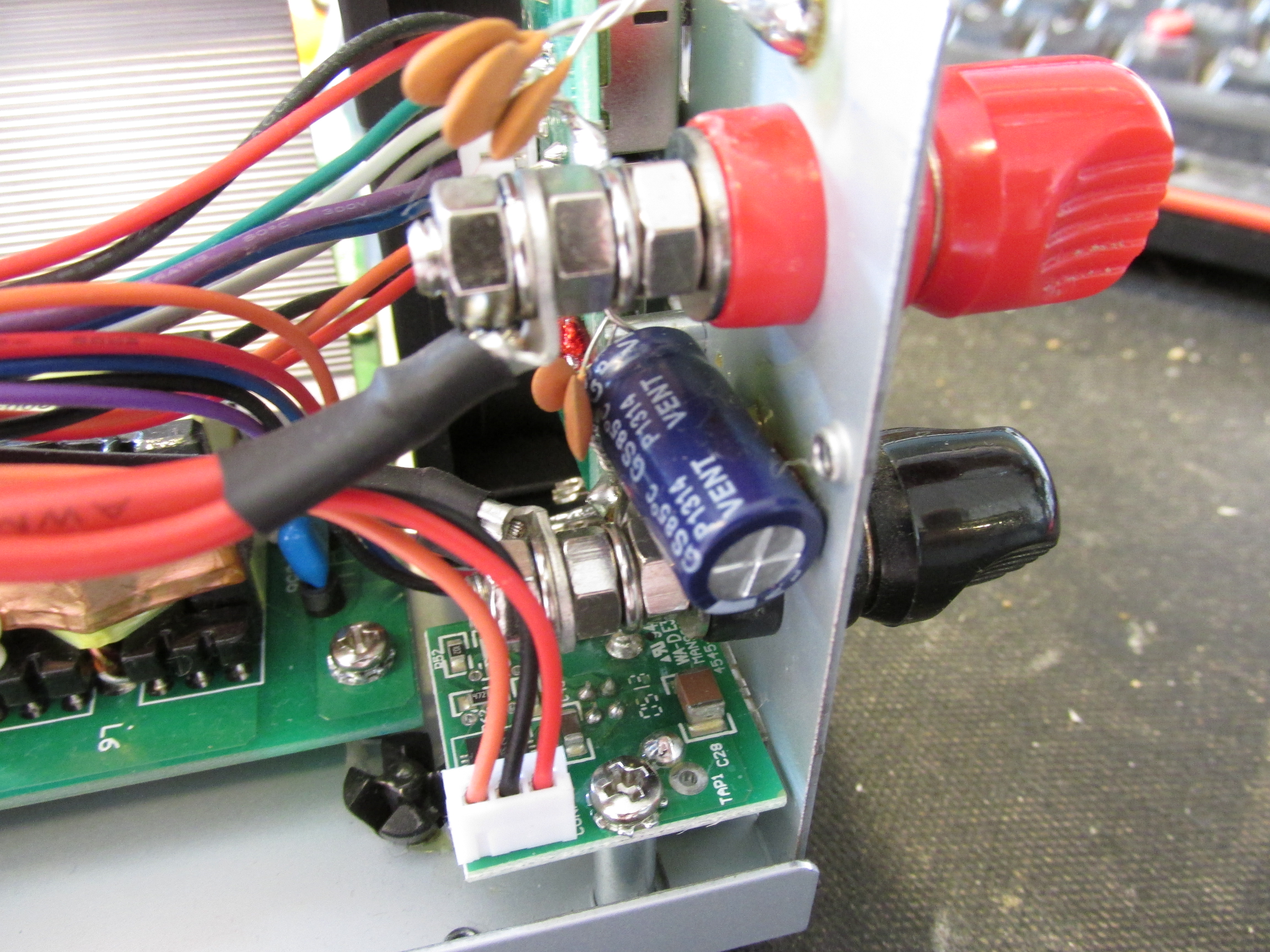
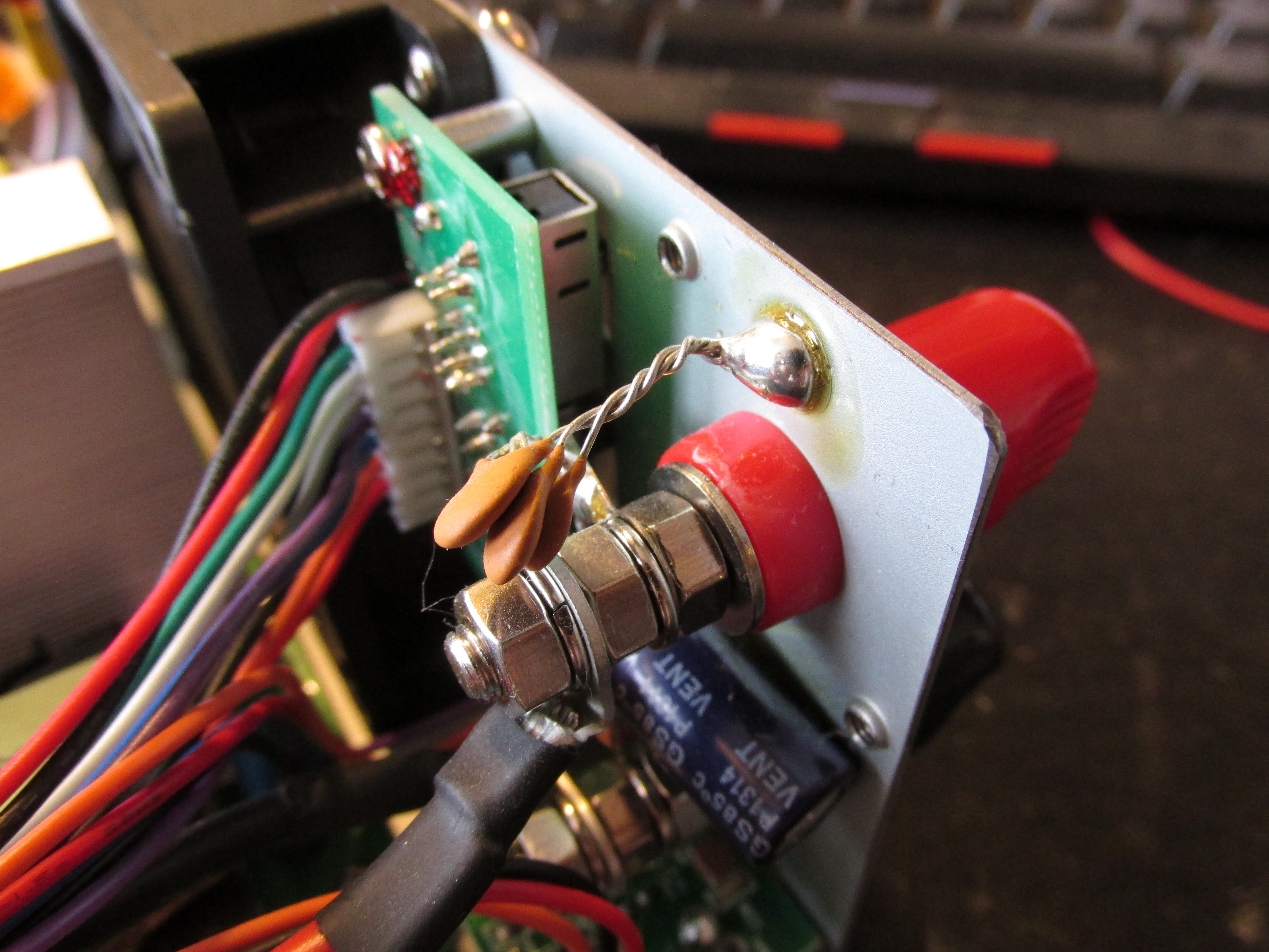
There are a few cables that connect the boards, but all are concentrated to a one place, and nicely tied together. Some caps are mounted directly on the terminals, and some of the ferrites are loose and I had to glue them a bit better. It’s actually much better than I expected!