When working with mains voltages, one needs to be very careful not to be electrocuted. Isolation transformer can help mitigate the risk (but will NOT make it safe), and as I had none, I decided to build one myself from two UPS transformers.
The mains voltage is earth ground reference, so if you are in contact with earth ground (and you usually are, as are most devices like computers, power supplies or even oscilloscopes), the current can flow through you. The isolation transformer’s secondary winding is not earth ground referenced, and thus the current won’t flow from either winding’s and to ground and you can feel a bit safer.
Be careful though, because once you start measuring with anything earth ground referenced (bench multimeter, oscilloscope), you just referenced the circuit to earth ground again, and though the measuring equipment is safe, you are not. Even if you don’t measure, you can still electrocute yourself by touching two different points in the isolated circuit!
Usually, one needs 1:1 transformer capable of handling the voltage and current needed. As I had none, I decided to use two huge UPS transformers, and put them back to back to make the 1:1. The efficiency is probably not very good, since the voltage is first dropped to 24V and then raised again to 230V, and the currents in the 24V circuit will be huge; nevertheless, it works, and here is the schematics:
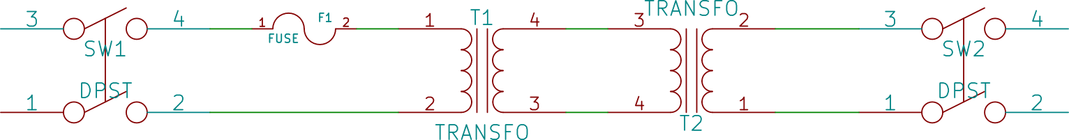
Schematics
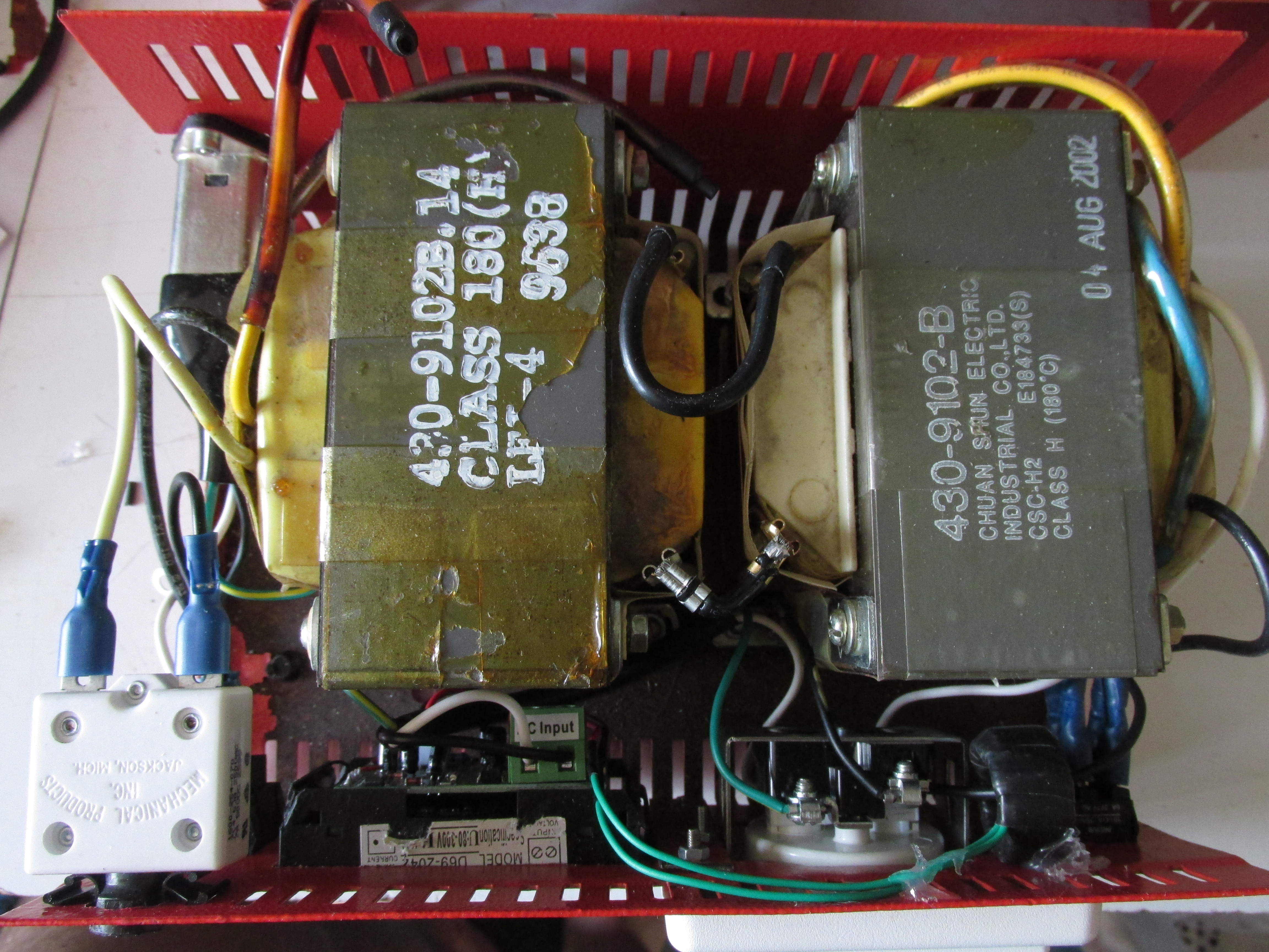
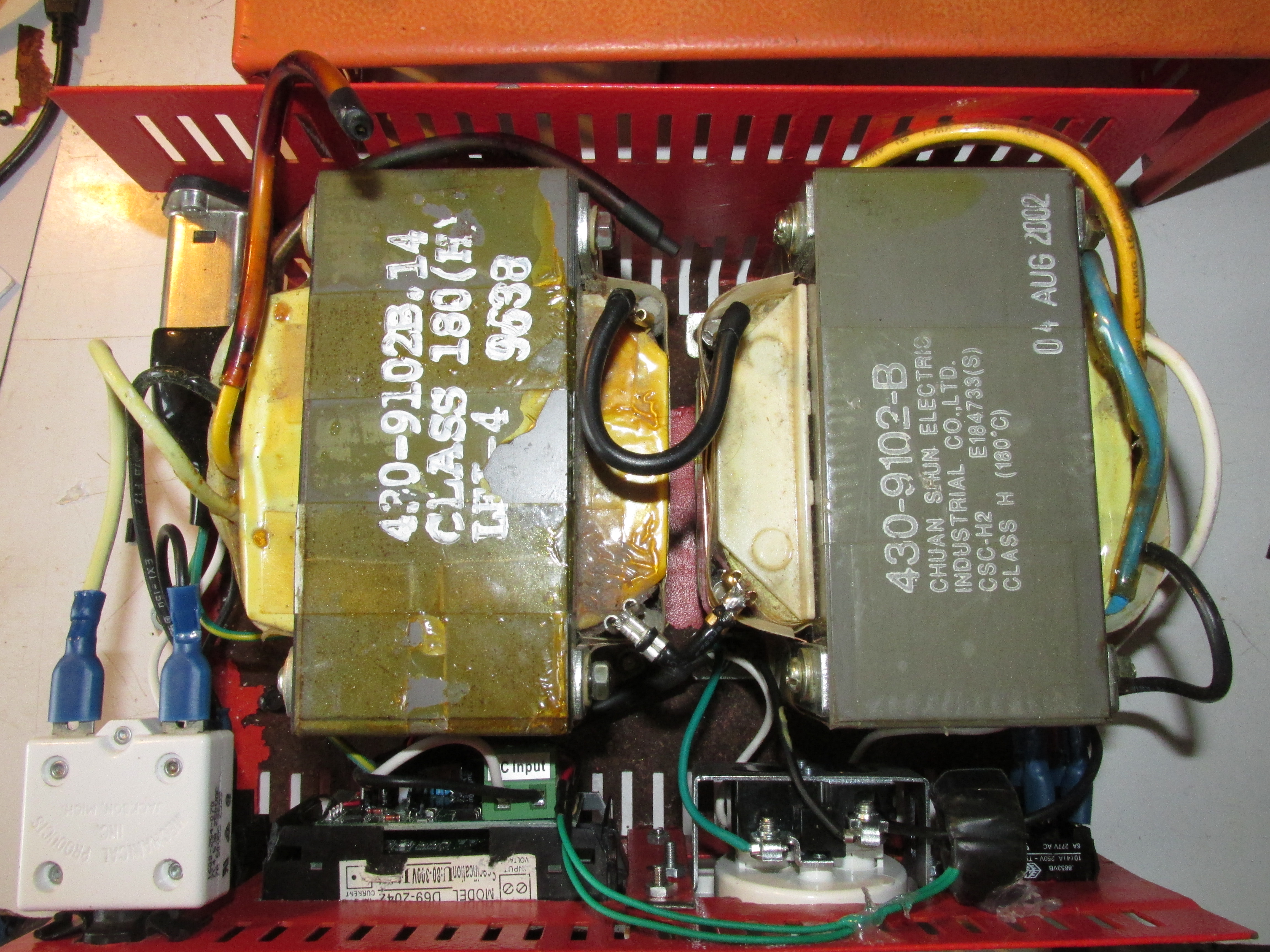
The transformers have three windings, one is primary and connected to mains voltage (1-2 on schematics). The two others are secondary: one of them is capable of large currents (3-4 on schematics) and the second is probably feedback (not shown in the schematics). You can recognize the primary winding by it’s higher resistance (around 4.6 Ohms for my transformers). The secondary windings should have extremely low resistance (significantly lower than 1 Ohm).
I used two switches, one on the primary and one on the secondary side, and replaced the fuse with mechanical circuit breaker (I had no suitable fuse holder at my hand). The fuse/breaker should be rated approximately to the transformer capability, since it protects it. My does not, since it’s 7A, but I will fix that once I’ll buy proper fuse holder.
For the build, I modified an old case from lead acid battery charger, which is robust and just large enough for the transformers and mains socket to fit inside.
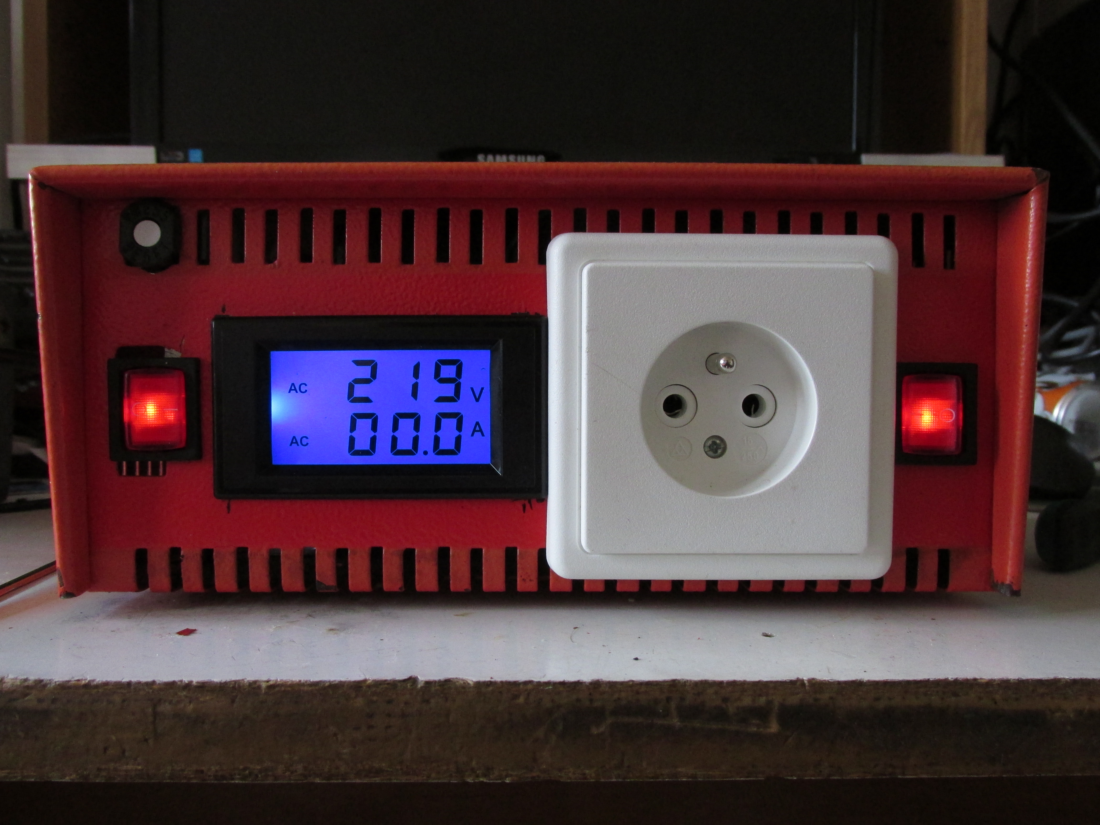
I started with the transformers, switches and input/output sockets (standard IEC connector from ATX power supply, and standard european socket for the output), mechanical circuit breaker and as a bonus, I added a cheap AC volt/amp meter from ebay.
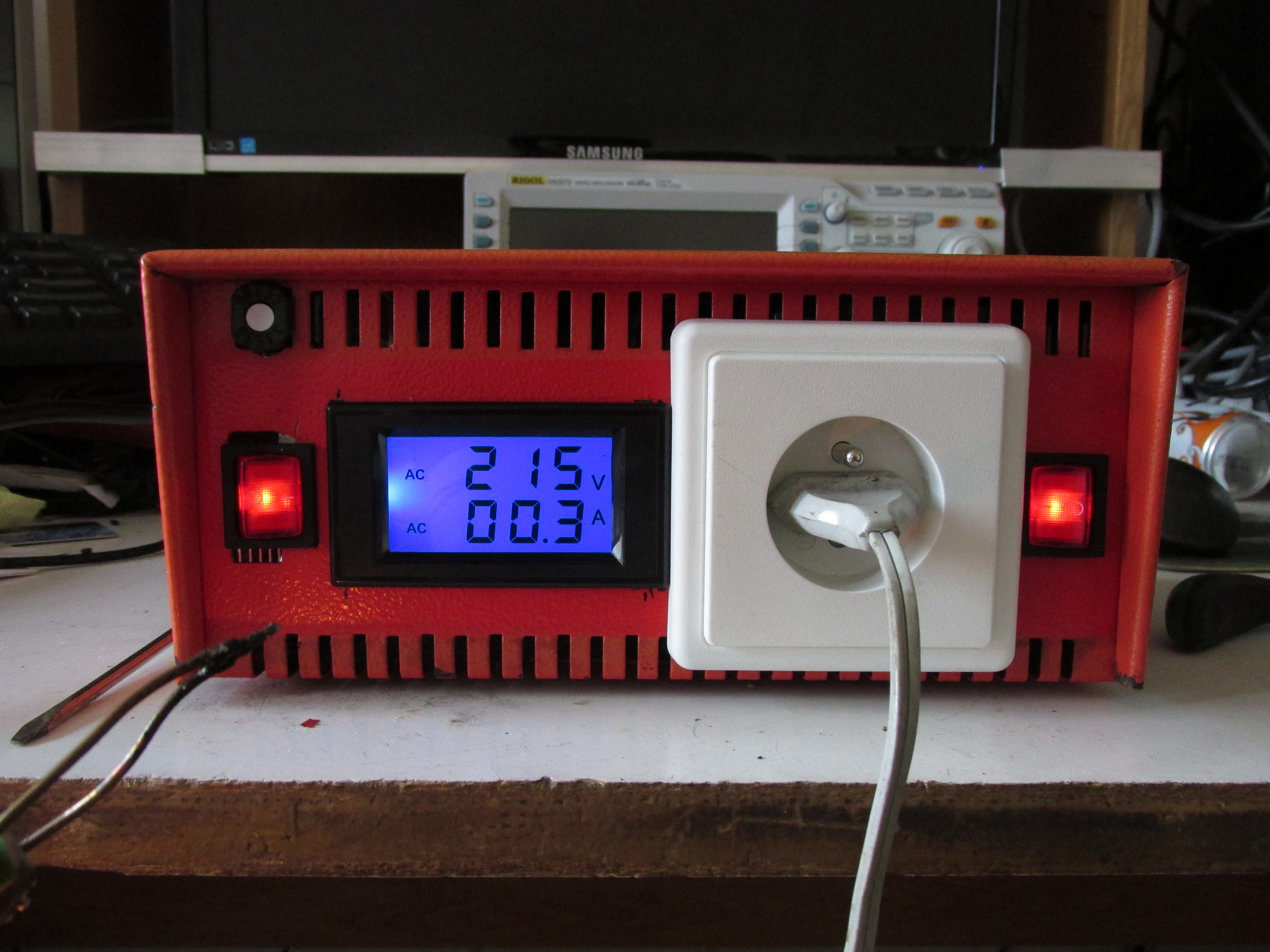
The meter is rated at 300V/100A. Unforuntely, the amp range is way too much (1-2A would be enough), but I could not find one with lower rating (and high enough voltage) for cheap. Other than that, the meter is quite nice, it’s powered from measured voltage and comes with a current transformer and works even with low currents, though I don’t expect the precision to be any good, but gives me an idea about the power consumption of the device plugged in.
The performarnce is good enough, the transformer has open-circuit voltage around 220V (that is 10V drop) and drops another 5V under ~100W load. That is well within tolerance for most device, and I will rarely need more power.