I bought a Garmin Chirp, as I was interested in what makes it tick, and wanted to make a custom one, possibly with a bit more (interactive) functions.
| Pad | MSP pin | Name |
|---|---|---|
| 1 | 39 | D/AVSS |
| 2 | 1 | DVCC |
| 3 | 9 | P1.5 |
| 4 | 36 | TMS |
| 5 | 37 | TCK |
| 6 | 35 | TDI/TCLK |
| 7 | 1 | DVCC |
| 8 | 34 | TDO/TDI |
| 9 | 14 | P2.2 |
| 10 | 32 | P4.6 |
| 11/RST | 38 | RST |
| TXD | 22 | UCA0SIMO |
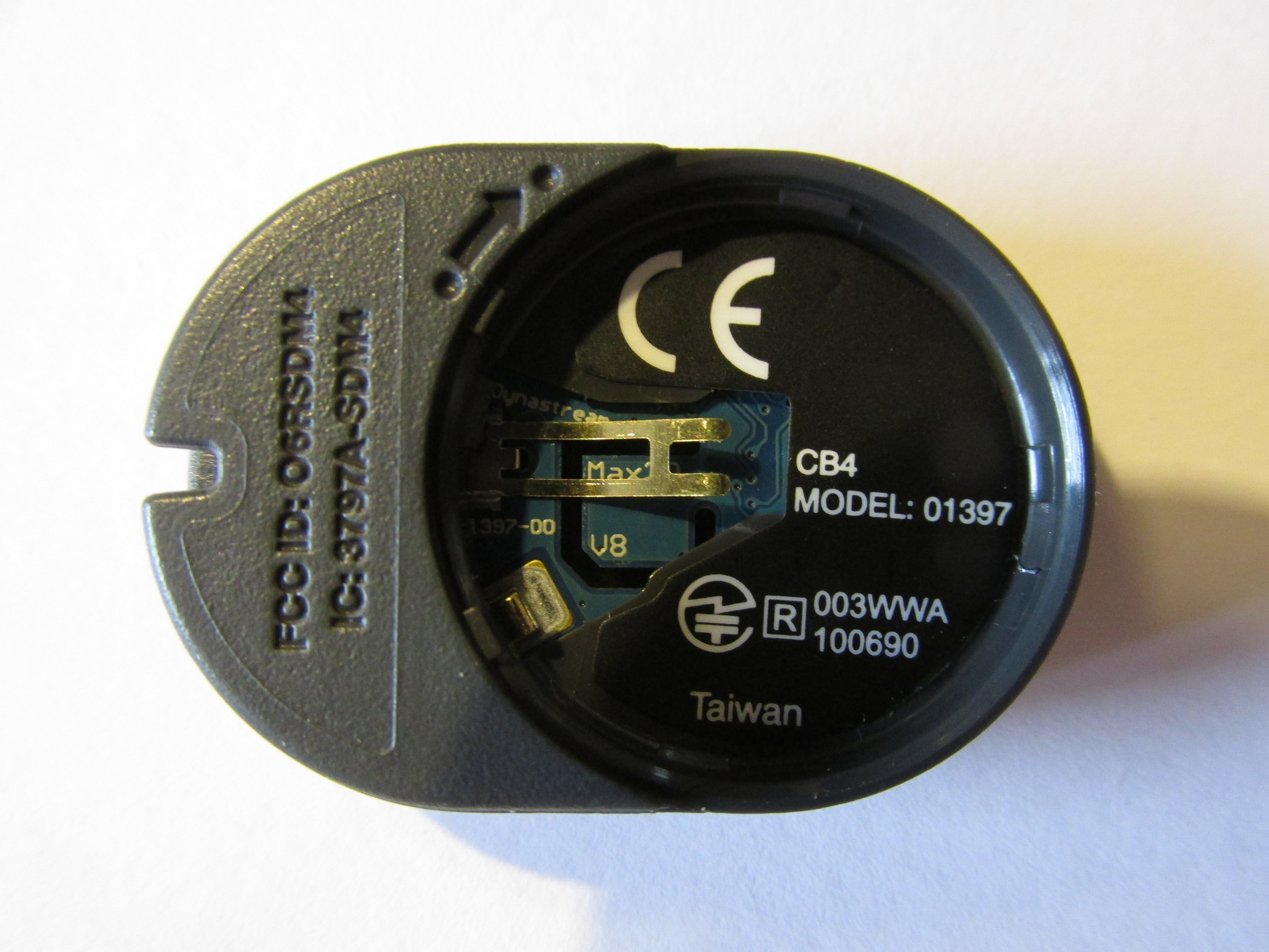
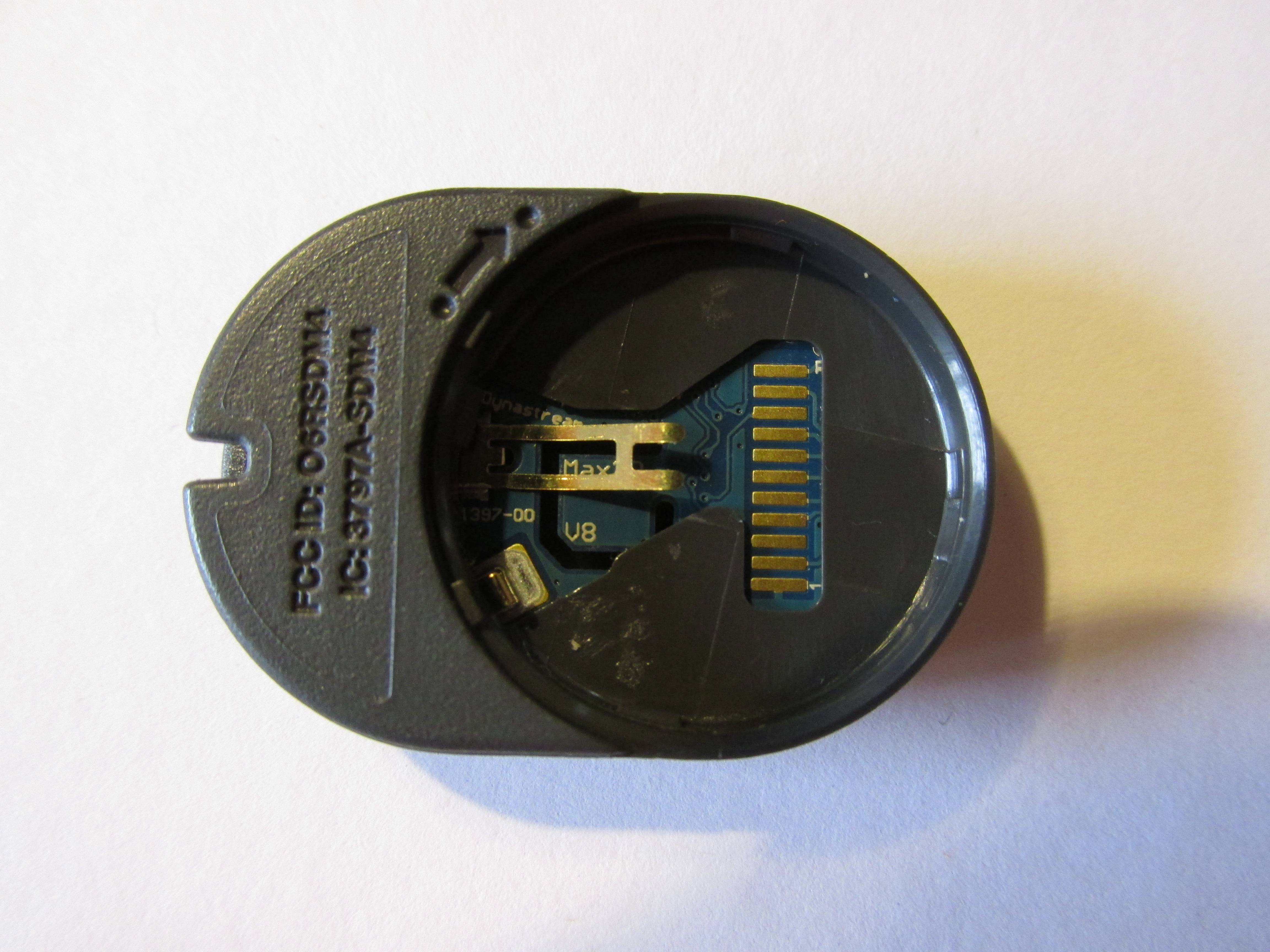
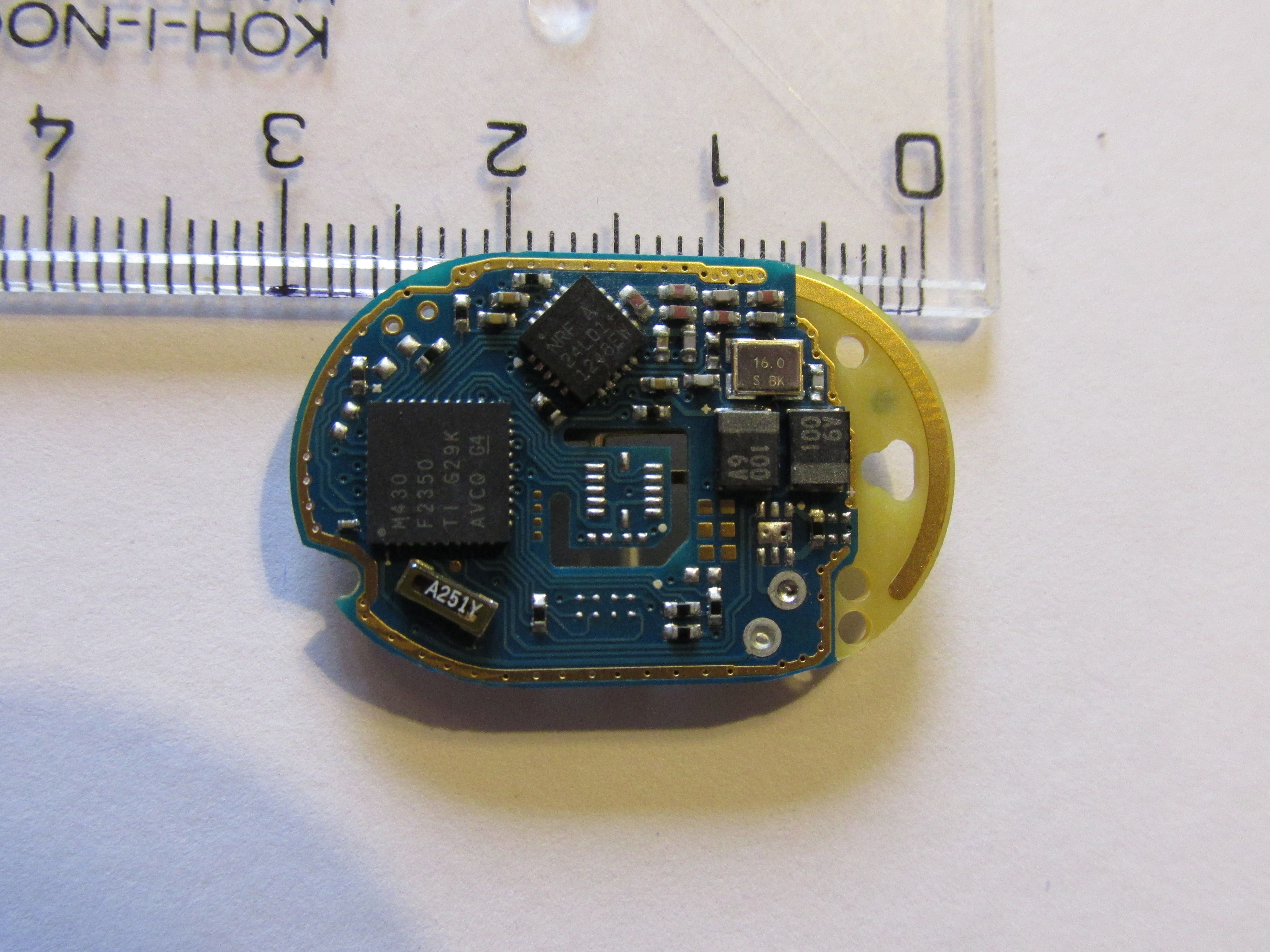
The device is really small, about 3.3 x 2.3 cm, the battery compartment (single CR2032) is watertight, with a screw lock. If you take off the sticker, there are 11 exposed pads, with 1mm spacing, containing the JTAG and power pins for the IC (mapped on the right, pin 1 is clearly marked with “1”).
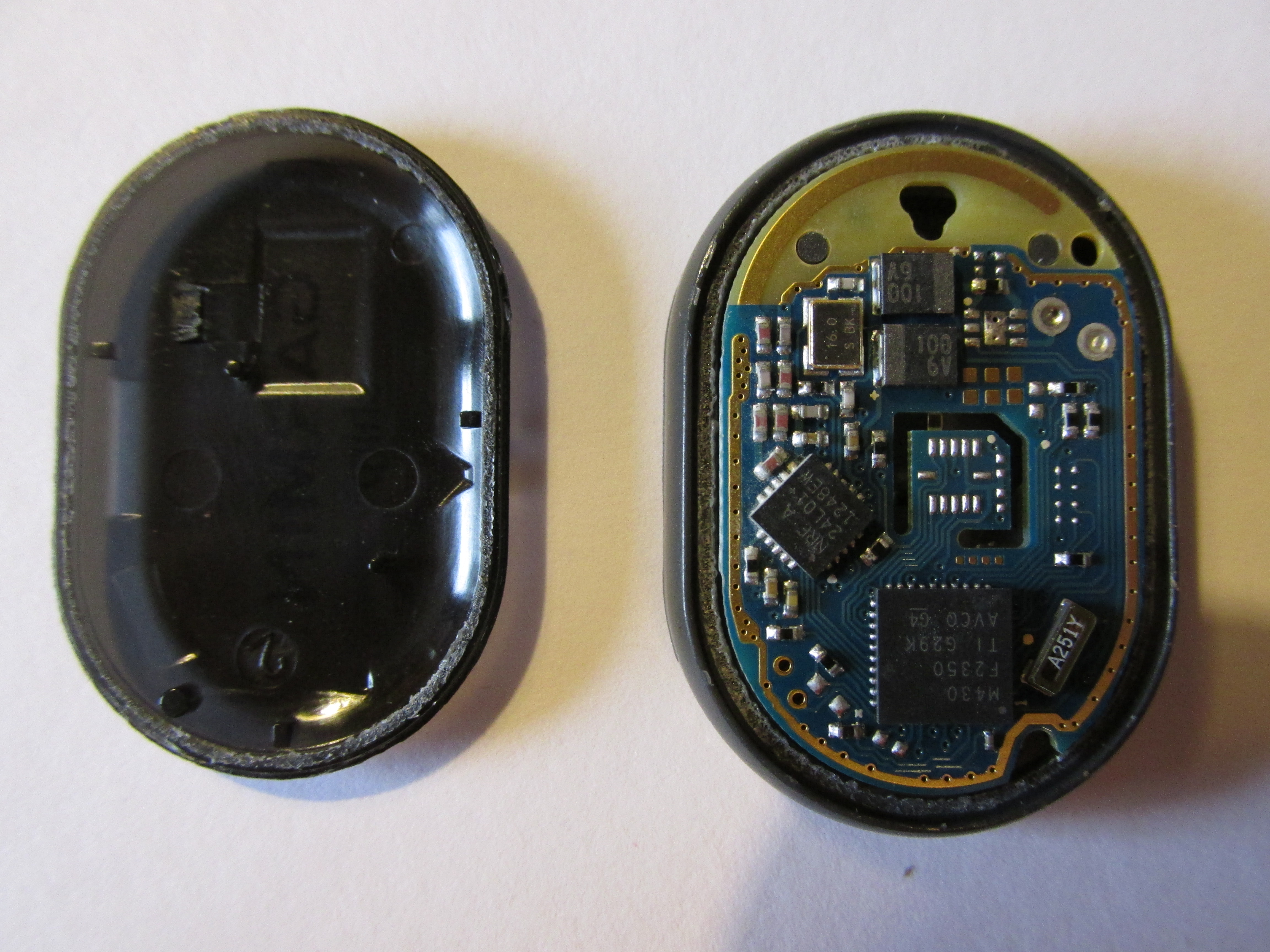
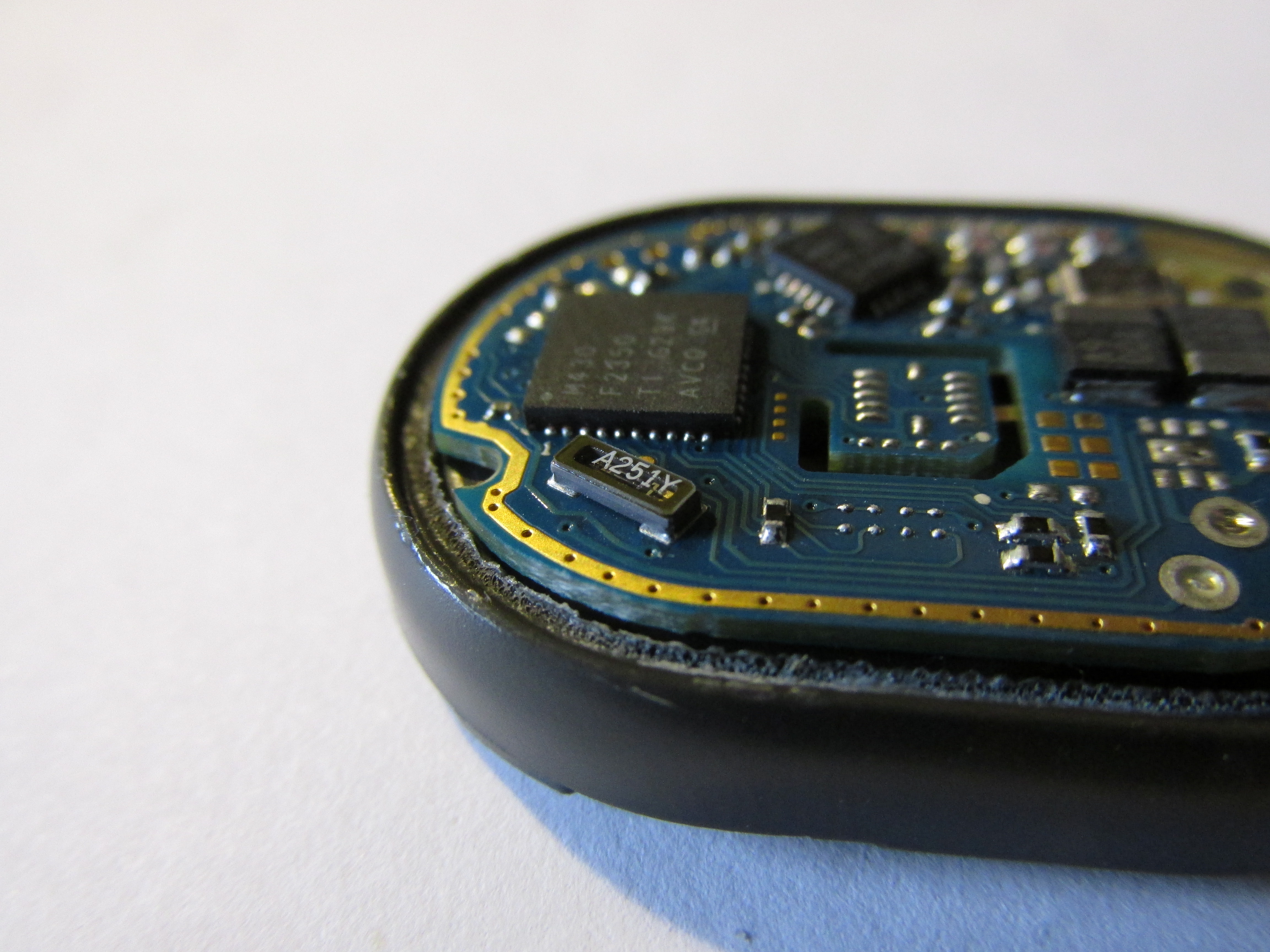
Getting to the rest is not easy. The semi-transparent cover is glued to the body, and needs to pry it off lightly. I used an old knife from all sides and it went off eventually without much damage.
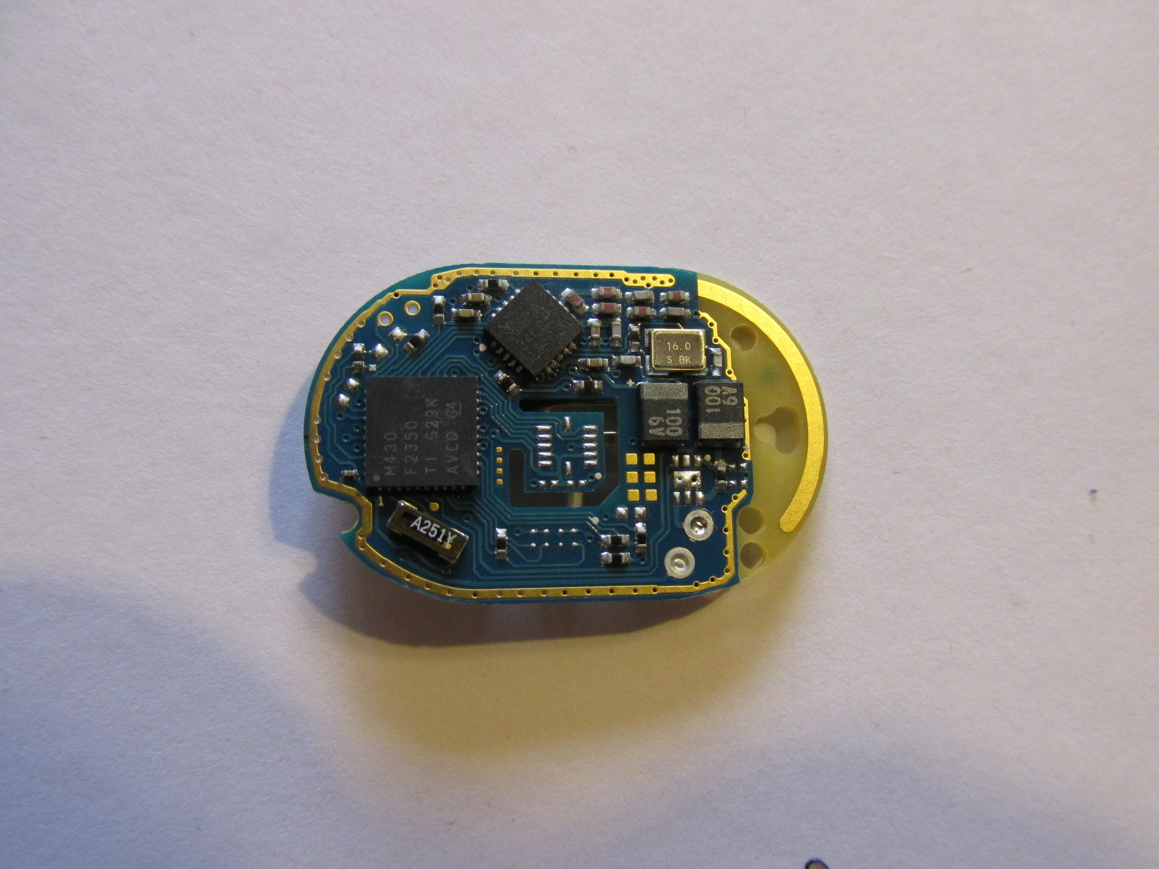
Inside there is a small PCB with MSP430F2350 and NRF24L01+, and little bit more besides a few resistors and capacitors. Interestingly, there are blank footprints for a few more ICs that are connected to the MSP430 processor. I guess they are the same PCBs for other similar products.
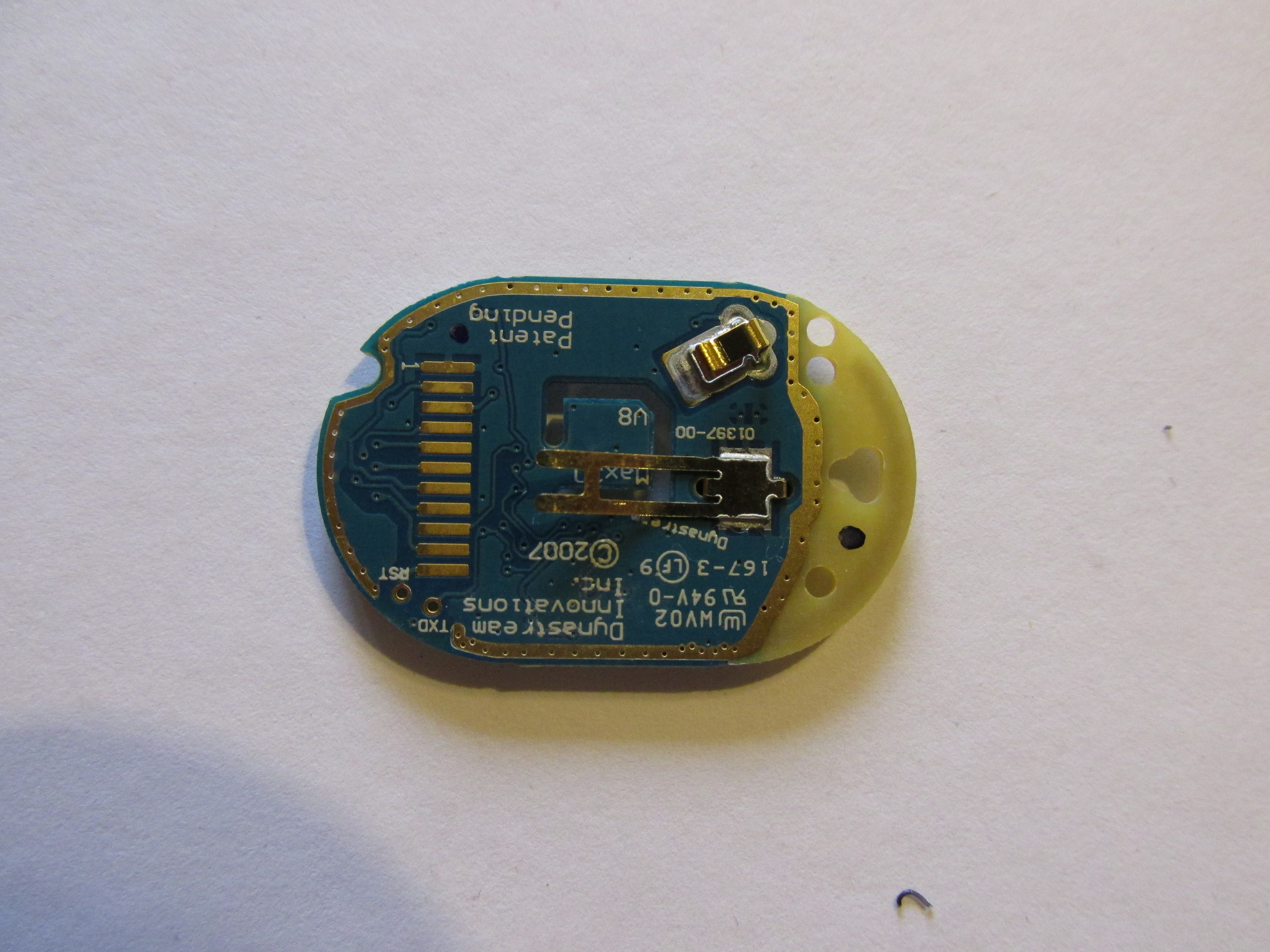
One more thing is revealed after the PCB is taken out, and those are two holes marked as TXD and RST. The RST is same as RST on the JTAG connector, but the TXD is connected to the serial line between the NRF and MSP. That will be easy sniffing!
I’ll be making more experiments with chirp later, but for now, if you want to get started, you can get the specs at thisisant.com (you’ll need to register first), including the geocaching beacon profile spec!